You’re new to machine vision. You know you’ll need a camera and lens, but when you open the Edmund Optics catalog (or start surfing the web,) you’re overwhelmed by the options. So, in keeping with my mission of providing practical advice to machine vision users, here are a few tips:
The task dictates the hardware. Don’t buy a camera because you like the color, because there’s a pretty girl in the catalog or because it has more megapixels for the buck than any other camera. Start with the task.
Define the field of view – the area that you need to image. Don’t worry about fitting it to the proportions of the sensor (16:9, 4:3 or whatever,) just determine length and width, or diameter if that’s more appropriate. (Incidentally, I prefer to work in metric units – I just find it makes life easier.)
Now, a word of caution: Never plan on using every pixel in the sensor. This is because optical distortion and a fall-off in light intensity make the border pixels less reliable. To avoid using these I suggest adding 10% to the longest dimension you need to view, and calling that the field of view.
Now you need to determine the resolution required, in terms of pixels per millimeter. Okay, this can cause some head-scratching so let’s dive a little deeper.
The drivers for pixels per millimeter are either the smallest feature you need to detect, OR the required measurement resolution. If you need to check the presence of a screw in an assembly, then the smallest feature you need to find is that screw head. But how many pixels does it take to do that?
People have tried to apply some science to the business of how many pixels make a feature detectable but I prefer to rely on old-fashioned heuristics. (That’s “rule-of-thumb” to you!) The absolute minimum number of pixels needed to find a feature is a square measuring 3 pixels by 3. But, if it’s a circular feature you need to find this can result in only the center pixel fully covering the feature. The border pixels will have a grayscale value partway between that of the feature and the background, making detectability difficult. Thus 4 by 4 pixels is better and 5 by 5 better still.
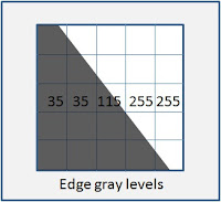
Now, how about measurement resolution? Without going in to how an edge is detected, let’s just say that calculation of edge location depends on the gray levels of the surrounding pixels. And you can’t assume that the edge lines up neatly with the pixels; you’ll never have a white pixel adjacent to a black pixel – there will always be one or two shades of gray in between. So my heuristic for edge detection is that the uncertainty in the measurement will always be 3 pixels.
 But before you apply that to the tolerance on the part print, remember this: you almost certainly have two edges to find in your image, so the total uncertainty is 6 pixels, not 3. And how is this related to the part tolerance? Well opinions vary, but I suggest that the measurement uncertainty should be no more than 10% of the tolerance on the dimension. So if you’re measuring a feature that should be 25mm +/- 0.6mm, (I picked those numbers to make the arithmetic easier,) the uncertainty should be 0.060mm, meaning that you’ll want each pixel to span 0.010mm.
And with that number, you can calculate how many pixels are needed to image your field of view.


3 comments:
These are definitely good heuristics for starting the discovery of the resolution of the camera to use, and how the size of the field of view plays a role.
Lately I have been queried about angular measurement resolution within a vision system. After pondering, researching and calculating I have determined a method for caluclating the nominal accuracy of an angular measurement, but I don't know that I am convinced it is realistic. Of course it will ultimately depend on the ability of the software tools and calibration, etc. but are there any heuristics for predicting the nominal resolution of an angular measurement.
When you speak of angular measurement, are you referring to:
A) Looking at two edges in a 2-D image and calculating the angle between them? or...
B)Looking at two objects within the camera's field of view and calculating the angle between the two imaginary lines connecting the center of each object to the camera lens?
The first I think of as plane geometry, the second more like what astronomers have in mind when they speak of the angular distance between two stars, etc.
Spencer
I am concerned with the scenario in choice A. While calculating the angle between the edges is easy enough, how does one predict the nominal accuracy of the measurement? Measuring a part of known value will obviously be the method for verifying the accuracy of the measurement. However how does one decide on the camera resolution and size of field of view to approximate a desired accuracy?
Post a Comment